
Back |
Interactive 3D PDF of Carnegie Stage 18 |
The interactive PDF below has been very kindly provided by Dr. Jill PJM Hikspoors, Prof. Wouter H Lamers,
Department of Anatomy & Embryology, Maastricht University, Maastricht, The Netherlands
Contact: jill.hikspoors@maastrichtuniversity.nl
Publication: 10.1038/s42003-022-03153-x
*Important* Although some web browsers will allow PDFs to be viewed online, the file must be downloaded and saved to a computer to enable the interactive options.
 |
 |
 |
 |
|||
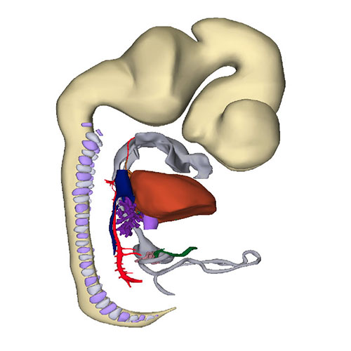
Right-sided view |
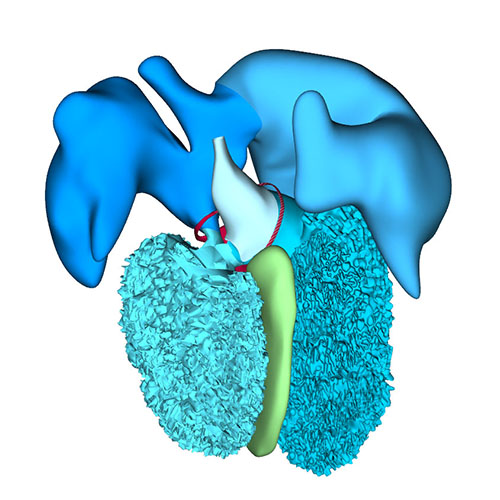
Right sagittal view: Visualizing secondary foramen and small interventricular foramen |
Cranial view: Interventricular foramen components (tricuspid gully, intermediate and subaortic part) are well defined |
Right view: Changing arterial pole |
|||
 |
 |
 |
 |
|||
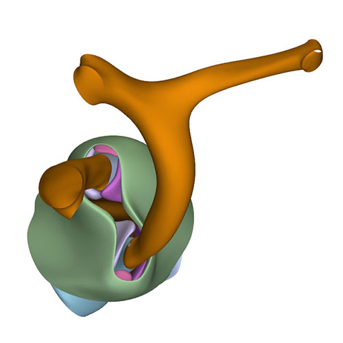
Left cranial view: Adjacent and non-adjacent leaflet formation |
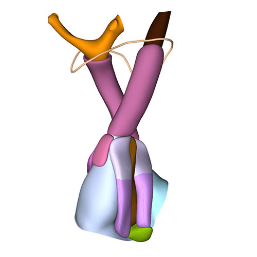
Dorsal view: Rotation of the arterial trunks relative to each other and asymmetric growth aortic trunk |
Ventral view: Changing position of the right ventricle |
Left cranial view: Position of the pulmonary and aortic channels |
At this stage, ~43 days have passed since fertilization. Compared to the previous stage, the venous part of the heart has only changed to a limited extent. Pectinate muscles, first identifiable as small stubs of the inner myocardial layer at CS14, now begin to expand in both appendages. The primary atrial septum and the secondary foramen remain comparable to the previous stage. Cardiomyocytes are now populating the dorsal mesenchymal protrusion, or vestibular spine, and the mesenchymal cap to form the well-developed ventro-caudal muscular rim of the atrial septum. The diameter of the pulmonary veins has increased further. Reflecting atrial growth, the myocardial atrioventricular canal changes in appearance from tubular to funnel-shaped, becoming transformed into the vestibules of the atrioventricular valves. The position and relative size of both lateral endocardial cushions in the canal did not change.
While the structural components that are responsible for ventricular septation become morphologically identifiable, the right ventricle gradually begins to occupy a more cranial position relative to the left ventricle. The junction of the left ventricular inlet and outlet, with the latter still represented by the peri-subaortic component of the interventricular foramen, is guarded mainly by the superior endocardial cushion. The lesser curvature, forming the cranial margin of the foramen, is still muscular. The junction between the right ventricular inlet, known as the tricuspid “gully”, and the outlet is formed by the fusing superior and right-lateral endocardial cushions. By this stage, only a small connection, representing the middle part of the original interventricular foramen and also known as the tertiary interventricular foramen, remains between the cavity of the right ventricle and that of the root of the subaortic outflow tract. This middle part of the interventricular foramen is bounded ventromedially by the muscular ventricular septum, dorsolaterally by the fused proximal ridges of the outflow tract, and dorsally by the fusing rightward margins of the atrioventricular cushions. The location of the borders of the right ventricular (tricuspid) inlet and left ventricular (subaortic) outlet parts of the original interventricular foramen can still be visualized by the shape of the GlN ring. Because its subaortic portion no longer expresses the epitope, we have assumed its position to be in the inner curvature, where it is found in embryonic chickens. The GlN-positive tissue in the septal structures identifies the location of the atrioventricular conduction system. In contrast to the relatively narrow atrioventricular junctions, the junctions between the ventricles and the bases of the subaortic and subpulmonary parts of the outflow tract are wide. The subaortic component of the proximal outflow tract, however, still remains positioned above the cavity of the right ventricle, but its cavity is now contiguous with that of the left ventricular outlet. This remodeling provides the left ventricle with unhindered vascular access to the subaortic outflow channel, thus allowing closure of the middle portion of the interventricular foramen to proceed, with closure completed at CS20.
The wedge shape of the myocardial component of the outflow tract, with its blunt side over the outer curvature, and the sharp edge in the inner curvature, becomes more pronounced. The septal and parietal endocardial ridges have now fused across their entire length. The distal-to-proximal fusion of the ridges occurs exclusively in the endothelium overlying the prongs of neural crest cells. The site of fusion is, therefore, marked by the dense central whorl of neural crest cells. The whorl subsequently disintegrates rapidly due to apoptosis, but some neural crest cells persist in the semilunar valves, with other remnants sometimes persisting as the so-called conus tendon. The temporary prominence of the neural crest may explain why its ablation interferes with septation of the outflow tract. Proximally, cardiomyocytes originating in the adjacent ventricular walls are invading the remaining mesenchymal shell of the fused ridges, thus forming a dumbbell-shaped muscular wall between the subaortic and subpulmonary channels. The myocardializing area is continuous on its medial side with the crest of the muscular ventricular septum and on its lateral side with the parietal wall of the myocardial outflow tract. This myocardialization occurs in mammals and birds. It progresses from proximal to distal, in other words, opposite to the direction of septation. In mice, myocardialization of the dorsal mesenchymal protrusion and the fused proximal ridges of the outflow tract both seem to be associated with apoptotic activity in the underlying mesenchymal layer.
Cup-shaped arterial valvar leaflets have formed in the distal part of the muscular outflow tract. The myocardial support provided to the still plump leaflets of the arterial valves may assist their closure. Growth of the myocardium in the middle outflow tract, however, slows further subsequent to formation of the arterial roots. The position of the arterial valves was previously put at the dog-leg bend. In reality, the arterial roots, containing the semilunar valvar leaflets, have significant length, and derive from the entire middle portion of the outflow tract. Their proximal boundary corresponds roughly with the dog-leg bend, which is present between the two parts of the myocardial outflow tract until CS16. At CS18, this boundary is marked by the transition of the thin layer of myocardium that surrounds the middle outflow tract into the much thicker myocardium of the proximal outflow tract. Their distal boundary, the sinutubular junction, corresponds with the distal end of the endocardial ridges.
The coronary arteries originate from an endothelial outgrowth of the aortic base. The stem of the left coronary artery is first seen at CS18, whereas that of the right coronary artery forms 2-3 days later at CS19. These coronary stems contact a periaortic vascular plexus which, in turn, contacts the ventricular coronary plexus. The main coronary trunks can be located in the relatively thick epicardial areas in the atrioventricular and interventricular grooves.
Distally, the arteries within the pharyngeal arches, along with the dorsal aortas, become increasingly asymmetric in distribution, with regression mostly seen on the right side. The artery of the right 6th arch has disappeared between the origin of the right pulmonary artery and the dorsal aorta. The right pulmonary artery, therefore, appears to arise directly from the pulmonary trunk. The right dorsal aorta itself tapers off between the origin of the 7th segmental artery and the confluence of both dorsal aortas, subsequently disappearing at CS20. Meanwhile, the walls of the large arteries become progressively better organized, which reflects increased expression of extracellular matrix proteins in this period.
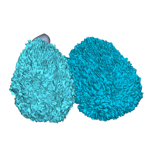
Click an image to download a 3D-PDF. The file must be saved to a computer to enable the interactive options. The 3D-PDFs can be opened on any computer as long as Adobe PDF or equivalent reader is installed.
A 3D-PDF becomes activated by “clicking” with the mouse on the reconstruction.
A toolbar appears at the top of the screen that includes the option “model tree”.
The model tree displays a material list of structures in the upper box, and preset viewing options (cameras) in the lower box. The sequence of items corresponds to that in Supplemental Table 3 of the publication.
The list of visible structures can be modified by marking or unmarking a structure.
To manipulate the reconstruction, press the left mouse button to rotate it, the scroll button to zoom in or out, and the left and right mouse buttons simultaneously to move the embryo across the screen.
A structure can be rendered transparent by selecting that option from the drop-down menu after selecting the structure with the right mouse button.
To inspect a combination of structures, one is advised to build up the composition, beginning with a familiar component, such as a lumen, rather than deleting non-relevant structures one-by-one from a completely reconstructed specimen.
The slicer button in the toolbar allows making cross sections. The plane of section can be adjusted with the offset and tilt options.
The “loop wires” in Supplemental Figures 3-6 of the publication, which are drawn through the center of the endocardial heart tube, emphasize the changing shape of the heart loop during CS10-13.
The side length of the scale cubes is 200 μm.
The preset views correspond to the images shown in Figures 1-10 of the publication.
Note that items that are visible in these views can be altered by marking or unmarking a structure in the model tree.